
A Comprehensive Overview of High-Speed Optical Communications
Scaling high-speed data movement from IM-DD to Copackaged Optics/Coherent/Silicon Photonics

Editor’s Note (6/1/26): Moving forward, I am transitioning this Substack into a deep-dive resource on System Architecture that covers the packaging, thermal, power, and signal integrity stack. To reflect the depth and combination of the synthesis involved, the deepest technical layers of my guides will now be reserved for paid subscribers.
Before each paywall, I’ll post links to some of my other adjacent posts that give you a well rounded flavor of the interactions amongst other domains.
In this post I will cover entire optical communications space:
I will introduce the conventional IM-DD optical approach with VCSELs used for short reach
I will then highlight challenges with scaling conventional IM-DD to higher data rates
Then I’ll explain techniques to improve data bandwidth:
🔒 Co-packaged optics
🔒 Silicon photonics
🔒 External modulation
🔒 Coherent optics
High speed optical interconnects have become one of the hottest markets in AI data centers. As bandwidth demand rises, the challenge is no longer just computing on data faster, but moving it across packages, boards, racks, and clusters efficiently.
The optical space has exploded over the past few years with many companies and startups proposing solutions to tackle data demands.
But I want to step back and ask ourselves: what are the first principles challenges with scaling high-speed optical communications?
The workhorse for short reach - IM-DD & Pluggable Optical transceiver
The workhorse for short reach optical communications today are IM-DD with pluggable optical transceivers. Lets take a looks at what each consists of.
Intensity Modulation - Direct Detection
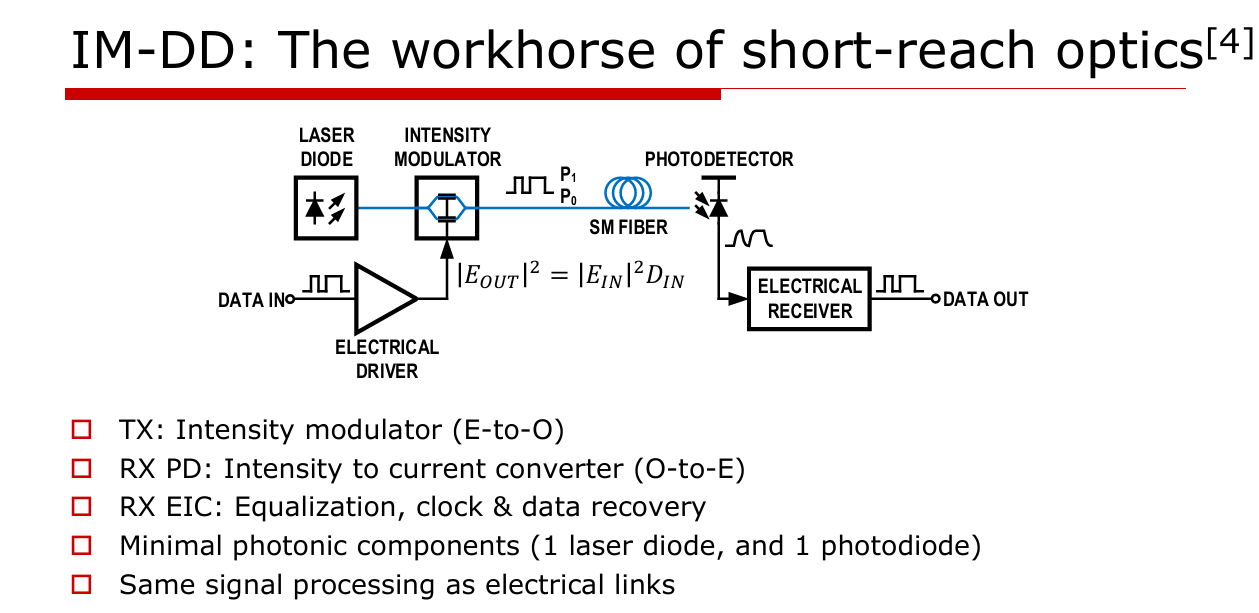
IM-DD is the workhorse of short reach optics. IM-DD encodes information in optical intensity (whether that be 0/1 or higher levels in PAM4) and recovers it through direct detection.
This intensity modulation can be performed in one of two ways:
Direct modulation - the laser is turned up/down by the electrical signal
External modulation - a driver modulates a steady optical carrier
Pluggable Optical Transceivers
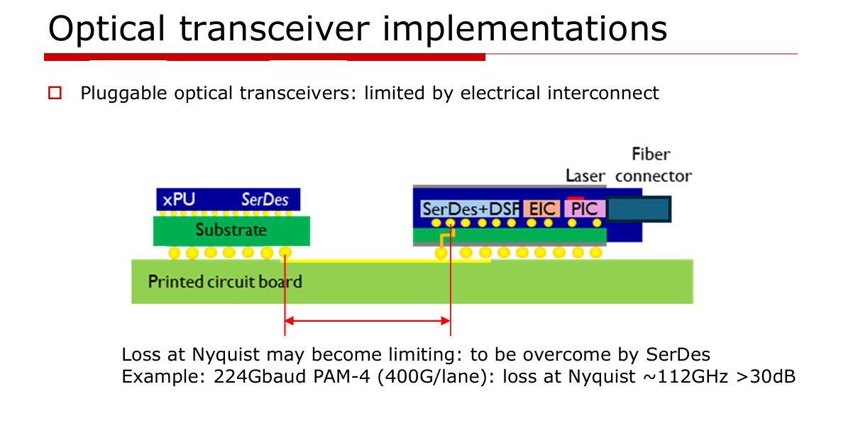
These IM-DD are typically packaged into pluggable optical transceiver modules that sit far away from the chip. These are are match-box sized modules that take in electrical (client) side data and convert it to optical (line side). Each block consists of following:
Serdes + DSP - For serializing / desterilizing the data from/to host and perform equalization
EIC - Electrical integrated circuit - consists of the electrical circuits fabricated in electrical processes (drivers, mixed signal conditioning, etc)
PIC - Photonic integrated Circuit - consists of the optical circuits fabricated in optical processes (Si Photonics, VCSELs, etc)
Optical transceiver modules are a very mature technology that has scaled in data throughput for many years. However, with AI workloads demanding 224+ GPBS throughput capability, the performance of the optical transceiver itself needs to adapt, as well as the signal integrity between host die and optical engine.
System architecture breakdown of a IM-DD
Next I will break down the architecture of an IM-DD in each of its components:
Transmitter
Fiber
Receiver
I will discuss several options for each and important design considerations.
TX Driver - Direct Modulation
Laser (Light amplification by stimulated emission of radiation)
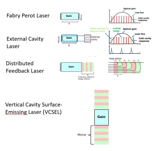
Lasers are powered by a large pump current stimulating emission. Photons with energy close to the material bandgap interact with electron - hole pairs and cause identical photons to be emitted. This causes an “optical gain” of photons within the active region.
This photons is then confined using two mirrors: one opaque, and other that is semitransparent to allow the light to shine through.
Lasing occurs when the pump current is high enough such that optical gain > optical losses.
Then, either a cavity structure or frequency selective bragg reflectors selects which optical modes are sustained.
In a Distributed Feedback laser (DFB) laser, a periodic grating of Bragg reflectors provides wavelength - selective optical feedback, favoring a narrow lasing wavelength. These Bragg Reflectors are highly tunable depending on the index of refractions and the lengths and # of sections.
VCSEL (Vertical-Cavity Surface-Emitting Laser)
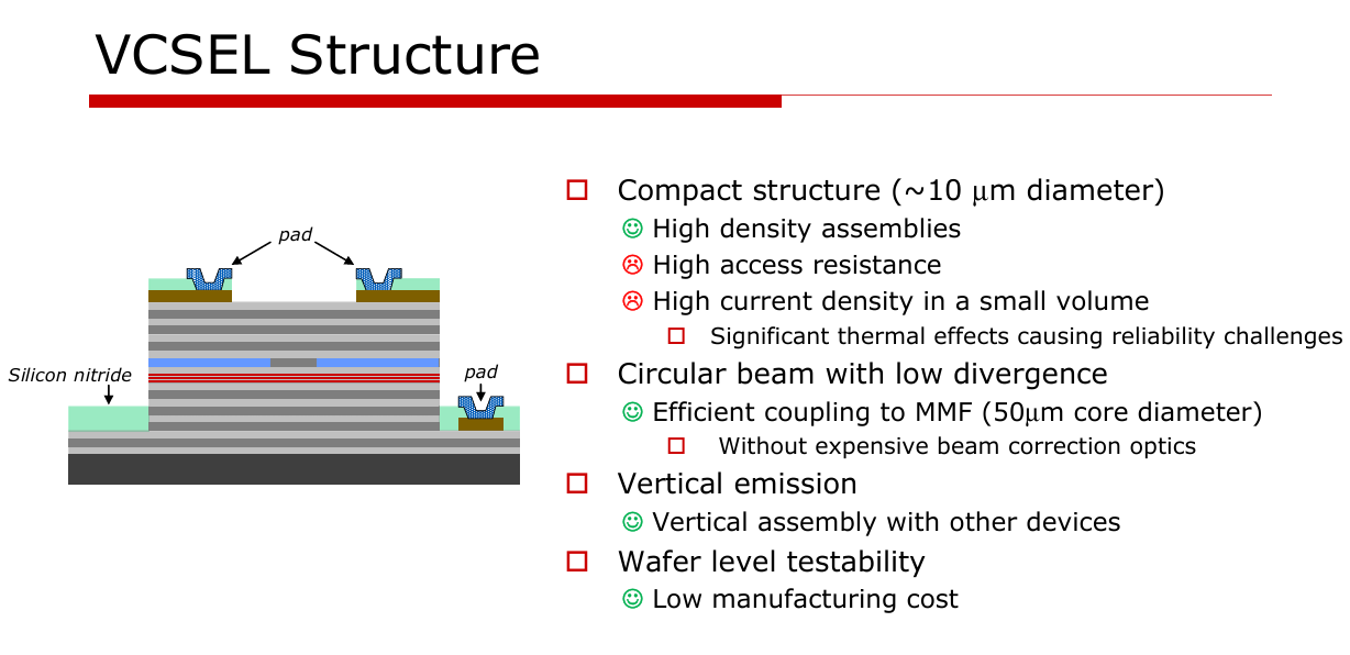
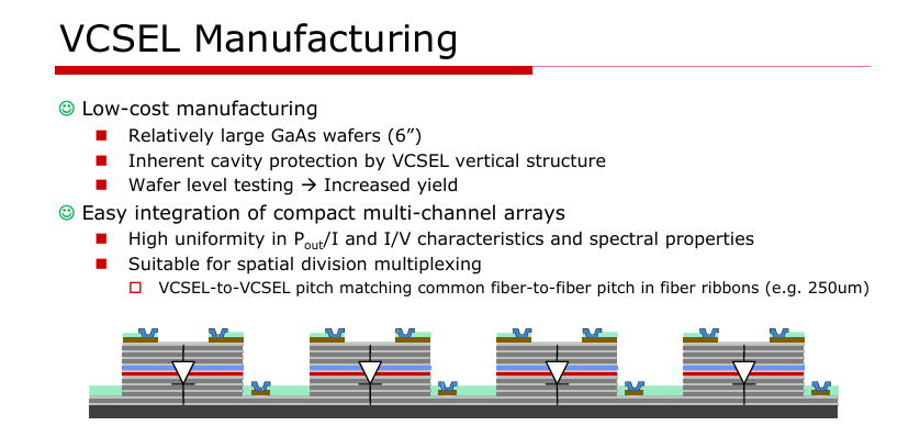
VCSELS are lasers that emit light vertically in a circular cross section. The active region consists of multiple quantum wells that enhances optical gain. Distributed bragg reflectors are stacked on the top and bottom of the active region with alternating refractive indexes. These layers are fabricated using epitaxial growth on a substrate.
The light is then confined with an oxide and current is pumped in through pads. The light is shown vertically above and redirected toward the optical fiber with optics.
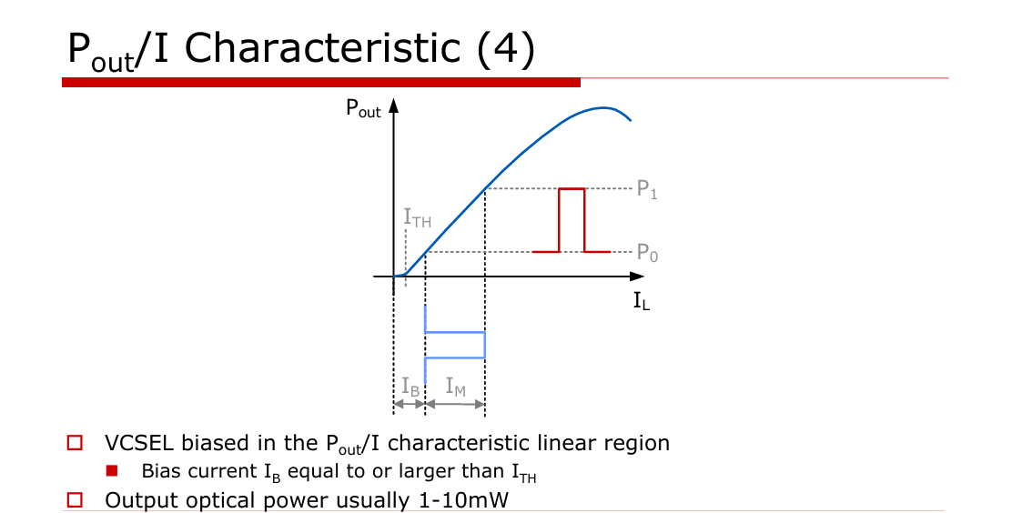
The Pout/I of VCSELs almost resembles a linear diode. The VCSEL begins lasing above a particular threshold current and exhibit a linear relationship between Pout / Iin over a useful operating region. Lasers require a DC bias to set the device in the linear region.
One important parameter is the extinction ratio, which is the ratio between P1 and P0. A higher extinction ratio is preferred as it improves BER margin to detect teh signal at the other end, but higher extinction ratios require higher currents, and therefore power, to drive the device.
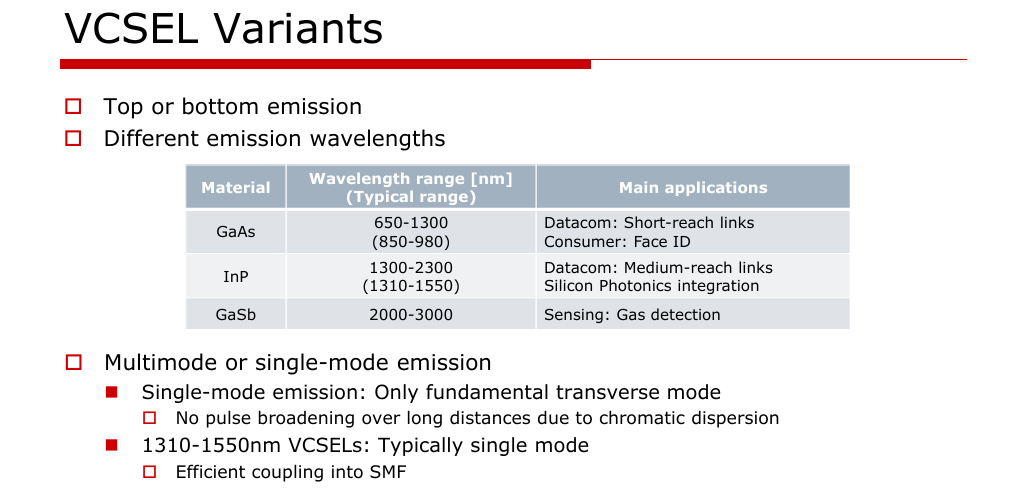
The two major materials used in lasers are GaAs or InP:
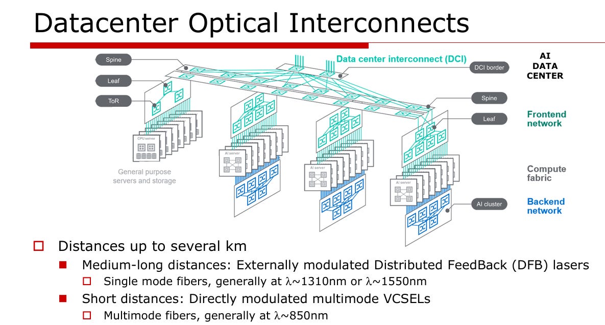
850 nm GaAs VCSELs are common for short-reach multimode links.
1310/1550 nm InP-based lasers/modulators are common where single-mode fiber, longer reach, or telecom/datacom bands matter.
VCSELs are very popular in short reach communications for a numbers of reasons:
Low cost manufacturability - they are easy to test on-wafer across multiple samples
Scalability - they can be formed in “arrays” to drive multiple optical lanes
However, VCSELs do have some drawbacks:
Reliability - issues due to oxide confinement and high currents degradating mean-time-to-failure
Signal switching nonidealities, including:
Turn on delay- a delay in the turn on of the signal that adds to latency
Jitter - uncertainty in the signal edge that degrades BER
Relaxation oscillation - an “underdamped” response in the turn-on characteristic that can affect BER and signal quality
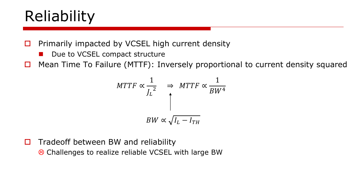
The main tradeoff in VCSELs is between BW and reliability. Higher current densities allow for higher BWs, but it also decreases the mean time to failure, a common metric used when evaluating reliability.
Driving the Laser
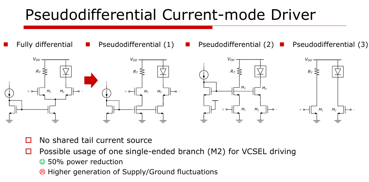
Here are a few DC coupled, common anode circuits used to to drive the laser directly using either fully differential or pseudodifferential to convert a voltage to a current to drive the VCSEL. There are other methods of driving such as common-cathode, BJTs, and push-pull implementations depending on the requirements of the system.
In general, the more VCSEL current that is needed, the slower the driver will be due to increasing output capacitance.
Fibers
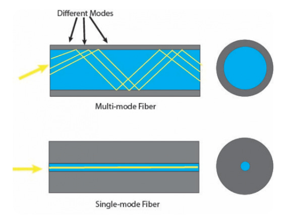
Multimode fiber optic cables are primarily constructed from silica glass (silicon dioxide). There are two major categories of fiber for high speed communications:
Multimode - Uses a larger core (50–62.5 um) to transmit multiple light paths
There are five classifications, OM1-5, that grade the quality of the fiber.
Pros: Cost-effective for short-distance, high-speed applications
Cons: Limited distance due to higher signal modal dispersion
Single Mode - Uses a smaller core (8-10um) to transmit a single mode of light
Pros: Low signal loss, avoids modal dispersion
Cons: Higher cost of laser components and more complex installation requirements
Generally speaking, multi-mode fibers are used for short reach interconnect due to its low cost and complexity. However, single mode fiber is being evaluated to “future proof” the data communications since it can support the higher BWs, though it adds to cost and integration complexity.
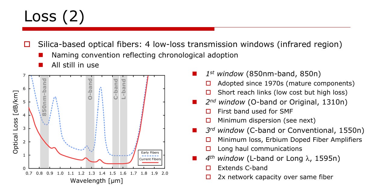
There are also four wavelength bands used in the fiber:
850nm band - used for short reach links
O-Band - 1310nm
C-band - 1550nm
L-Band - Extends C band to allow 2x network capacity
There are four major impairments:
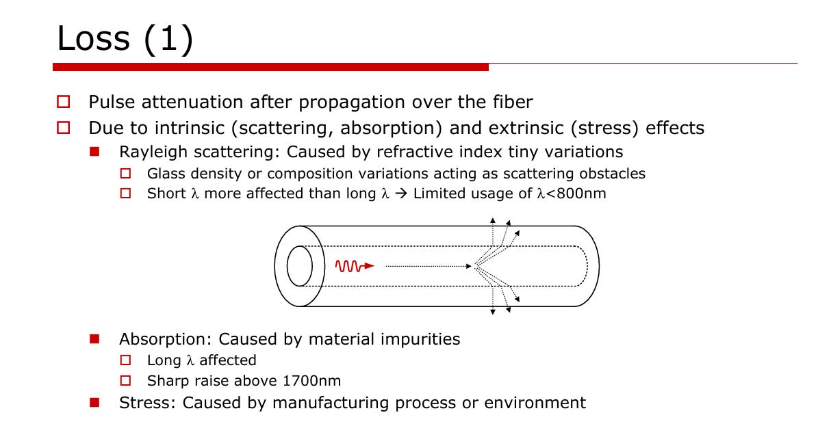
Loss. Losses cause pulse attenuation after propagation from a fiber. These are caused by intrinsic sources, including
Rayleigh Scattering
Absorption
Manufacturing Stress
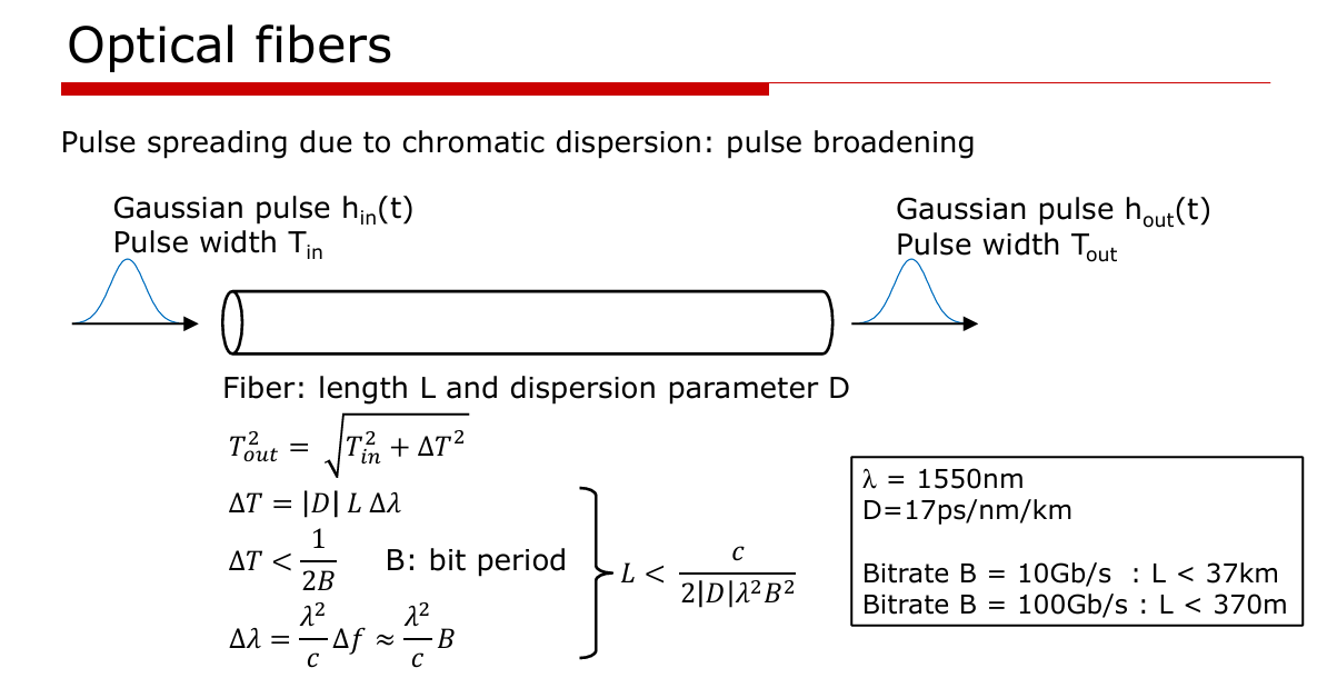
Chromatic Dispersion - pulse spreading after propagation over the fiber. This is caused by fiber refractive index dependence on wavelength
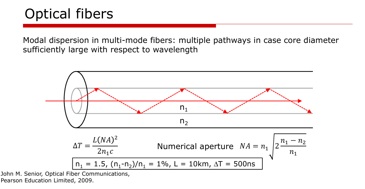
Modal dispersion - distortion due to different propagation delays of different optical modes. Modal dispersion matters in multimode fiber.
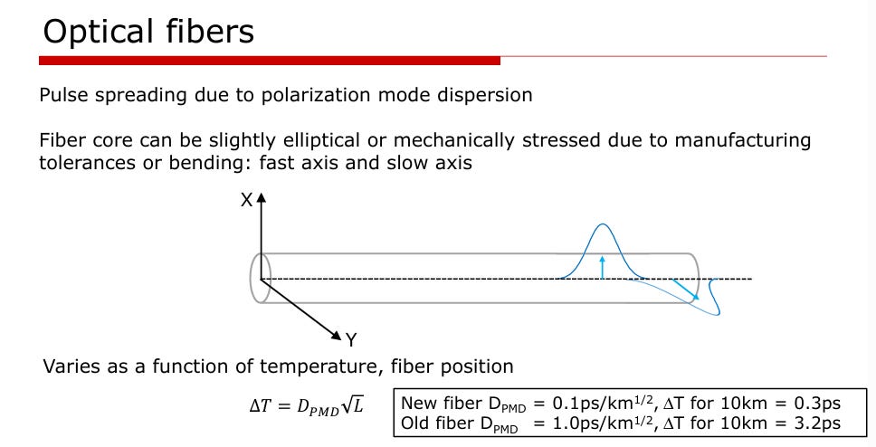
Figure 15. Polarization Mode dispersion in optical fibers [3] Polarization Mode dispersion (PMD) - dispersion cause by pulse spreading of different polarizations due to asymmetries in the fiber core.

Receiver - Photodetector
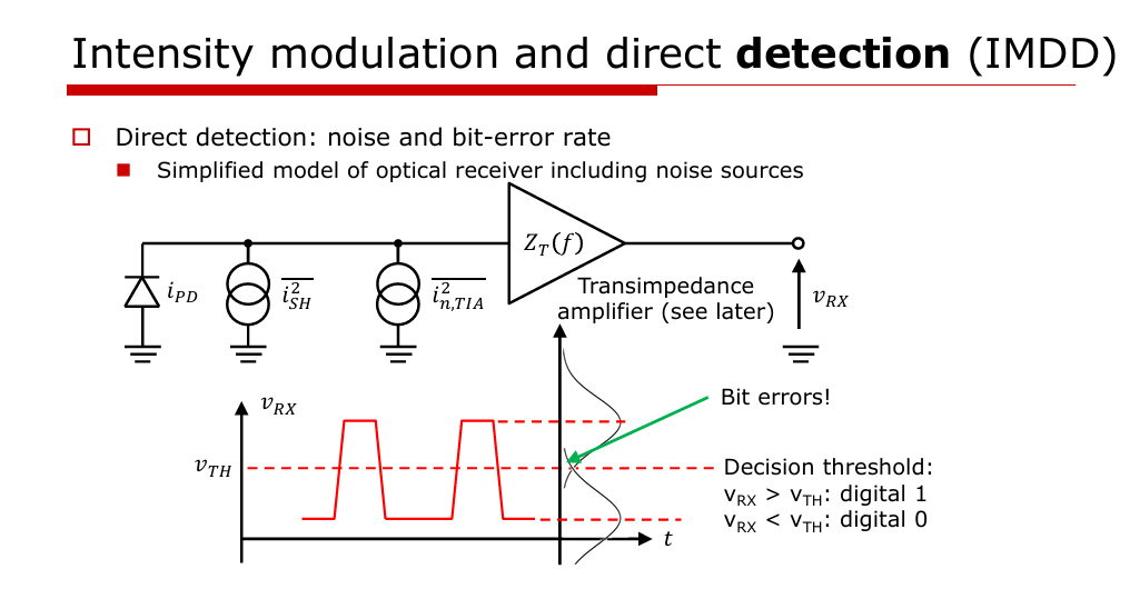
A photodetector consists of a Reverse biased PIN junction that generates current proportional to the detected light. The transimpedance amplifier then amplifies this current to an output voltage at the other end.
There are some important specs of this system:
PIN characteristics: Responsivity, capacitance, noise, dark current
Receiver Q-factor: The received signal level relative to total receiver noise
BER: BER can be derived from this Q factor: BER = 1/2*erfc(Q/sqrt(2))
A higher extinction ratio is desired to ease the burden on the receiver, but it does come with a higher power usage.
Why Scaling IM-DD is hard
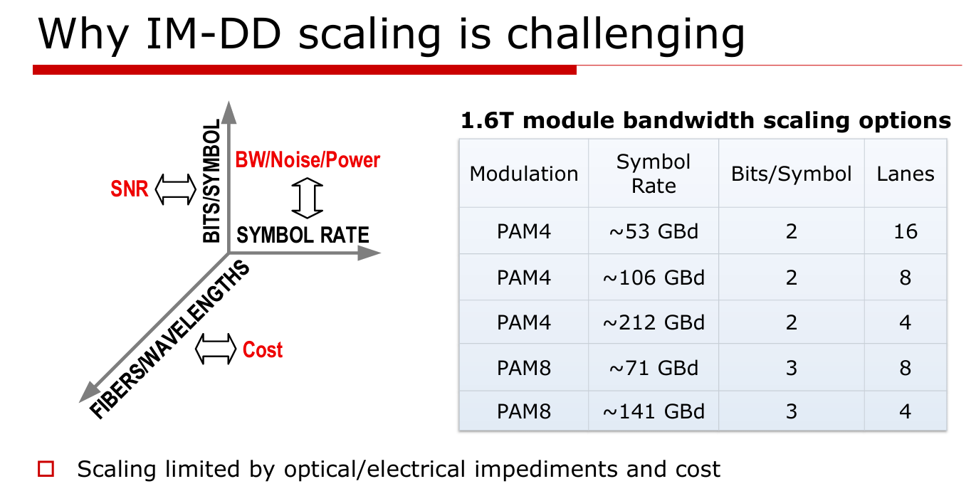
Scaling IM-DD to higher data throughputs is hard due to several unfavorable tradeoffs between BW, reach, noise, power, SNR, and cost. These include effects in both optical and electrical domain themselves:
Optical
Chromatic dispersion
Polarization Mode dispersion (PMD)
Nonlinear and interference effects
Electrical
Noise penalties at Higher BW
Tighter jitter, skew, and ISI
BW scaling limits in front ends
You can have the fastest optical transceiver, fiber, but its pointless if the signal can’t get to it fast enough. Not only the optical receiver itself needs to improve, but the signal integrity from the electrical interconnect is running into challenges shuttling high speed data back and forth. Solutions need to ensure that speed “bottlenecks” within the system scale with the system demands.
This leads to four major trends that generally increase complexity:
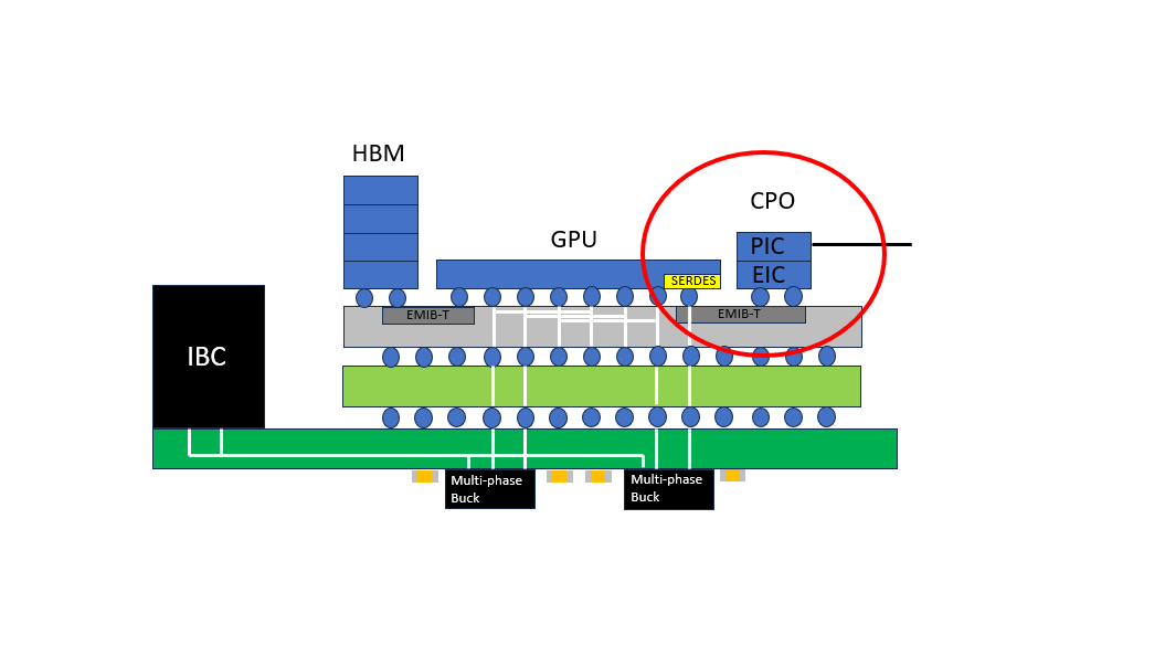
Co-packaged optics - embedding optical components within the package itself
Silicon Photonics - routing light through silicon waveguides and modulating it
External modulation - modulating a continuously running laser for higher BW
Coherent Optics - modulation amplitude and phase in the optical domain
After the paywall I’ll discuss these in further detail.
If you want to learn more about how optical communications interfaces with adjacent domains, consider checking out these other posts:


